Soldering Kit: Sensor


Soldering Kit: Sensor
Build a circuit that senses a change in a sensor while exploring the properties of this fundamental circuit, the Wheatstone Bridge.
This circuit is based on the properties of the Wheatstone Bridge and can be used to identify changes in resistance. Many sensors work based on a measuring a small change of resistance (temperature, pressure, light, humidity, TDS…) and the Sensor circuit allows exploration of these sensors.
What's Included:

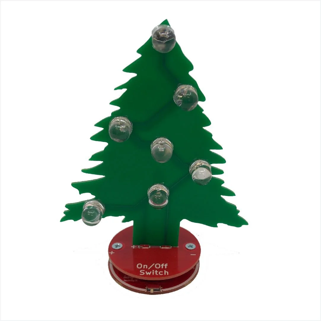
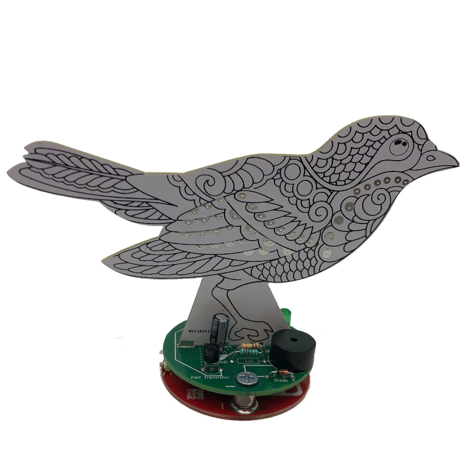
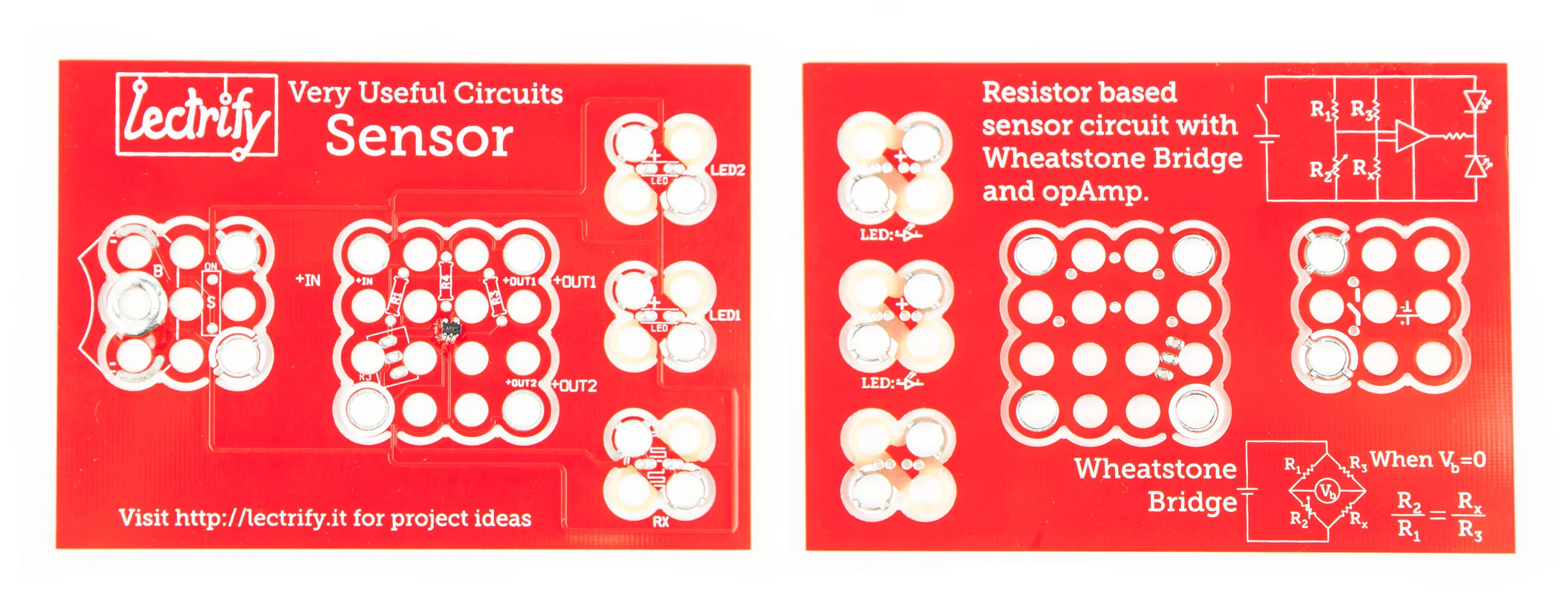
What does the Sensor circuit look like?

The Wheatstone bridge circuit has been used for over 150 years to identify unknown resistance or measure a change in resistance. Often, Resistors R1 and R3 are known values (often identical), Rx is unknown and R2 is a form of a variable resistor that can be changed until Vb is zero.
Resistance based sensors are commonly used as low cost means of measuring pressure, temperature, light, humidity, water quality and water quality.
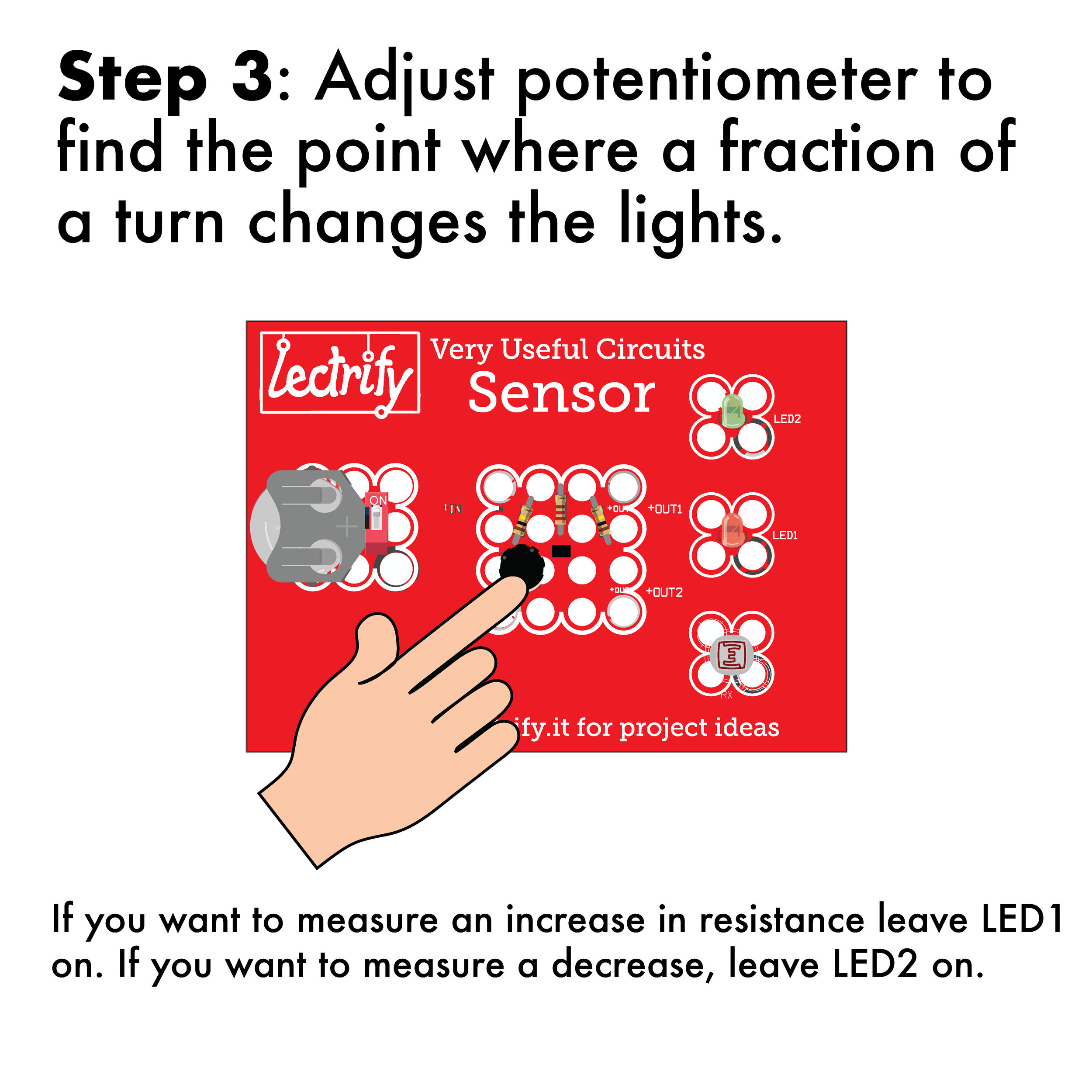
In the Sensor board circuit, R2 is a potentiometer that is used to balance the circuit. The Sensor also uses a Operational Amplifier (OpAmp) to amplify the change in voltage when the circuit is unbalanced. Because of the sensitivity of the circuit, it is near impossible for Vb to be exactly zero (which would be indicated by both LEDs being off.)
Soldering Instructions:


Project Ideas:

If the photoresistor is covered with a piece of opaque tape to make the resistance fixed, other objects can be tested for resistance. In the example above, a probe made out of a plastic straw and copper tape can be used to test relative conductivity of various objects.
Sensor is also available as a pre-soldered kit.